|
|


-- About
-- Contact
-- Diesels
-- Links
-- Layouts
-- Modules
-- Signalling
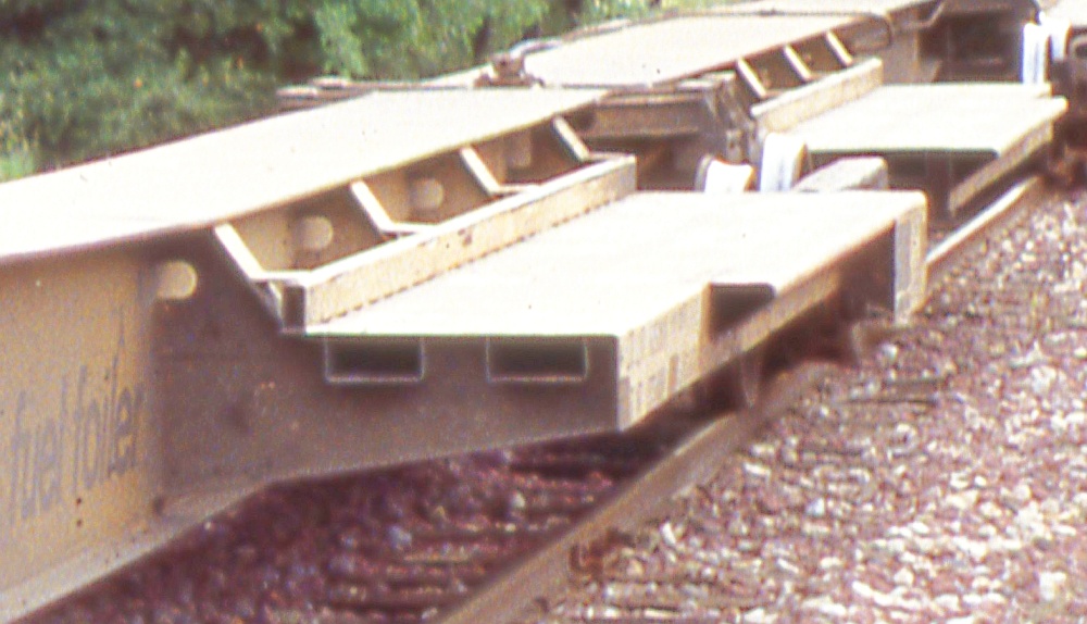
Below: A prototype photo showing platform structural details that I wanted to model, since they aren't present on the Athearn Impack kit:
- the platform supports angle downward to meet the centersill, and are "inset" such that there are flanges at top, bottom, and outside edges;
- two rectangular, hollow stiffeners running longitudinally under the platform top surface;
- a rectangular, hollow rub rail on top the platform at the inside edge;
- small, D-shaped cutouts in the supports where they meet the centersill, for routing through brake air piping;
- a triangular, hollow extension at the platform outside edge that widens the platform to handle 102" wide trailers.
ATSF 298993 Ft-93 10-pack Fuel Foiler Spine Car
3D PRINTED PARTS
With ten similar units in this car, it made sense to spend the time and effort designing custom parts in
FreeCAD and printing them with a high-resolution resin printer. And, these specific parts would have been very
difficult, if not impossible, to fabricate by hand from styrene, etc. I also enjoyed learning a new skill - 3D CAD
design (though admittedly I learned only enough to make these specific parts ... not an expert by a long shot).
I want to thank my friend Larry Goss for printing out these parts on his very nice 3D printer!
For clarity, the order of units is, from the brake end:
B-C-D-E-F-G-H-I-J-A
As with all freight cars, when facing the brake end with the brake wheel,
the car's "left side" is on your left and its "right side" is on your right.
entire website copyright Gregg Fuhriman
created with CoffeeCup Visual Site Designer
created with CoffeeCup Visual Site Designer
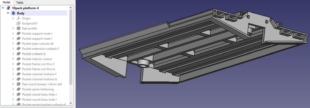
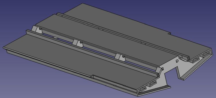
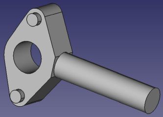
Right and Below: I used FreeCAD
3D design software to create my
parts. FreeCAD is an open-source
free tool with lots of how-to videos
for specific tasks. The software can
do much more than just 3D part
design, but I learned only enough
to make my 10-pack parts.
These are screen grabs of the
finished platform part, made up of
numerous surfaces and features.
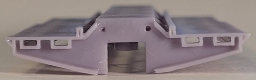
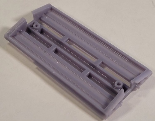
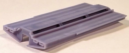
Above and Right: The fourth-round platform as printed by my friend
Larry Goss. I designed this part to directly replace the Athearn
platform part and fit snugly into the Athearn centersill.
All of my desired features are reproduced, including the small "D"
cutouts in all the supports on both sides.
I decided to not use the Athearn stamped-steel weights, as they
were visible through the open spaces between the supports, which
I didn't like. Instead, I filled the central channel with lead shot and glued
rectangles of lead sheet inside the trailer platforms.
The flanges printed a bit thicker than I'd like, but three rounds of test
prints proved that designing these any thinner caused "drop outs"
during the printing.
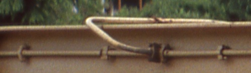
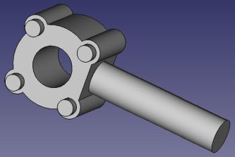
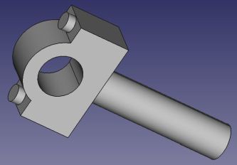
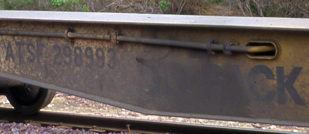
Right: This prototype photo shows an example of all three fittings I
designed in Free-CAD:
- The leftmost fitting I call a "pipe support" - it has a diamond profile
with two bolts, top and bottom. I also used three of these at pipe
junctions (third from left).
- The second from left fitting I call a "pipe junction" - it has a square
profile with four bolts, one at each corner. It's a bit thicker than the
other two fittings.
- The rightmost fitting I call a "pillow block" - it has a D-shaped profile with two bolts, top and bottom.
Below: Screen grabs of the 3D designs in FreeCAD. Each part has a mounting peg to glue into holes drilled into the Athearn centersills.
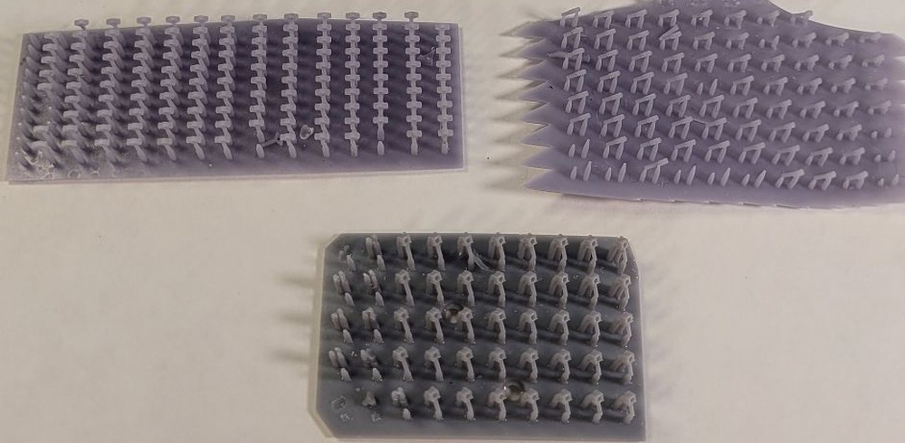
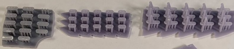
Below: The pipe fittings as printed by my friend Larry Goss, who used another software tool to replicate my
designs and add supporting structures necessary for resin printing. The parts easily pop off their supports for use.
designs and add supporting structures necessary for resin printing. The parts easily pop off their supports for use.
Units A, C, and D have oval slots through the centersills where brake piping or mechanical levers pass from one side to the other.
The slots have small flanges surrounding them. The Athearn model does not reproduce these slots/flanges, so I needed to come
up with a way to model them to reproduce the look of the 10-pack brake rigging.
Below: Unit A has a "small" sized slot where the train-line brake pipe passes through from the left side (shown here) to the right
side. This photo also shows examples of the "pipe support" and "pipe joint" fittings (see above).
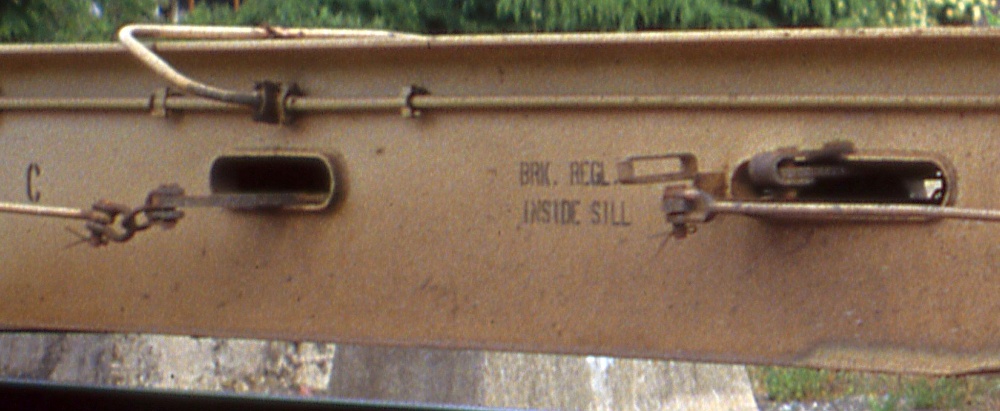
Below: Unit C has two slots where mechanical brake levers pass through from one side to the other. Note the rather complex
bits and pieces connecting the levers to the brake rods - I chose not to attempt designing all that into 3D CAD. Beyond my skills,
and I figured it would be too fine to sucessfully print and, even if it could, too fragile to hold up on a model.
This photo also shows examples of the three pipe fittings (see above).
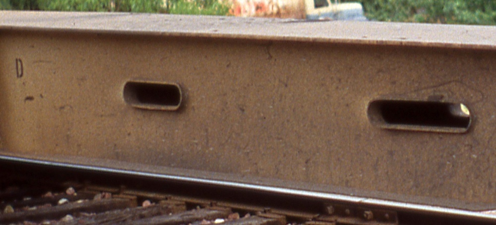
Below: Unit D has two "derelict" slots where mechanical brake levers once passed through - these levers were removed when Santa Fe
simplified the brake system. In comparison to the A unit slot, the left-hand slot is "medium" sized, and the right-hand slot is "large" sized.
simplified the brake system. In comparison to the A unit slot, the left-hand slot is "medium" sized, and the right-hand slot is "large" sized.
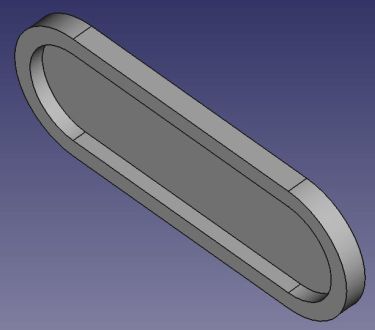
Left: The CAD design for the
"large" plain slot as used on
the D unit.
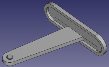
Right: The CAD design for the
"large" slot with lever as used
on the C unit.
I also designed a "small" plain
slot for the A unit, a "medium"
plain slot for the D unit, and a
"medium" slot with lever for
the C unit.
"large" plain slot as used on
the D unit.
Right: The CAD design for the
"large" slot with lever as used
on the C unit.
I also designed a "small" plain
slot for the A unit, a "medium"
plain slot for the D unit, and a
"medium" slot with lever for
the C unit.
My design solution was to make a very thin oval-shaped part with a raised flange
surrounding the outside. The part glues onto the centersill surface and the interior area
is painted black as a visual trick to suggest there is a slot in the centersill. For slots
with levers, I added a "half lever" protruding out of the part, with a small hole at the
end where a brake rod made of brass wire will be attached.
is painted black as a visual trick to suggest there is a slot in the centersill. For slots
with levers, I added a "half lever" protruding out of the part, with a small hole at the
end where a brake rod made of brass wire will be attached.
Right: Some of the finished printed
parts - medium plain slot, small slot,
and large lever slot.
These are so thin that the 3D
print supports caused small lumps
in the interior area, which I sanded
smooth once they were ACC
glued to the centersills.
parts - medium plain slot, small slot,
and large lever slot.
These are so thin that the 3D
print supports caused small lumps
in the interior area, which I sanded
smooth once they were ACC
glued to the centersills.