|
|


ATSF Model 40 Burro Crane 1771 and MoW Flat Car 206062
Ever since I built my Glen Frazer Free-mo module set with its maintenance-of-way (MoW) spur and loading ramp,
I've wanted a super-detailed Burro crane to display at the ramp. A piece of MoW equipment on a flat car spotted
at the ramp helps to self-explain the purpose of the spur's layout, which has a very short stub track where, at
the real Glen Frazer, the MoW equipment was switch-backed when moved between the ramp and main line.
This project likely holds the record for my longest build time from start to finish. I first started assembling the
Custom Finishing brand Model 40 Burro crane kit sometime around 2010 (I think). It's a difficult build, especially with
all the intricate cabling, metal components, etc. I didn't like how the cast-metal pulleys looked and attempted to make
my own from circles cut from sheet styrene. This quickly became tedious and, in frustration, I set this project aside.
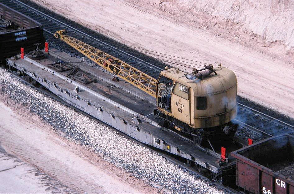
Below: This "down on" prototype photo by Mike Komo was a major inspiration and a huge help in building
and weathering the flat car including the various deck details. Thanks Mike for posting this photo!
and weathering the flat car including the various deck details. Thanks Mike for posting this photo!
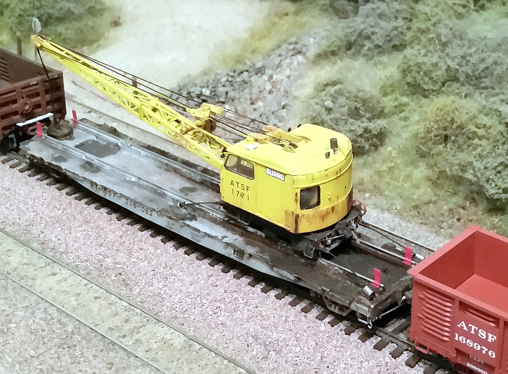
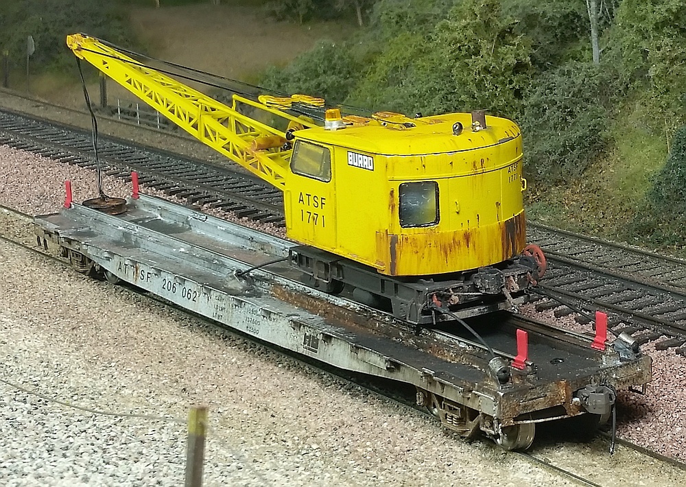
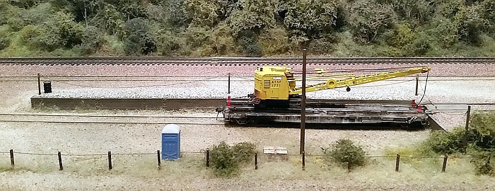
Left: Here is the model spotted at the
loading ramp on my Glen Frazer module.
It really completes the scene, and adds
a new focal point for viewers to enjoy.
In the future I hope to add some detailed
ATSF vehicles and maintenance figures
to give the scene more life.
Below: Just like the prototype ramp,
the flat car's coupler nestles into a
pocket built into the retaining wall.
This minimizes the rail gap for the
crane to negotiate when moving on/off
the car. Of course, my crane is fixed to
its flat car permanently, so this is just
for show in this case.
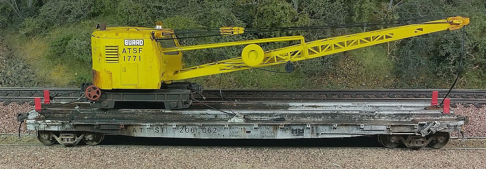
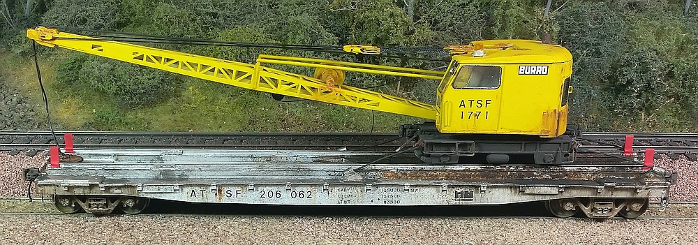
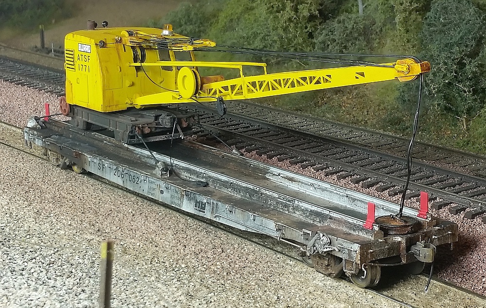
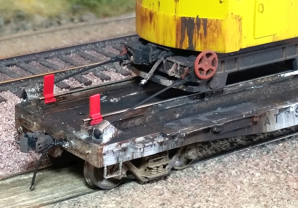
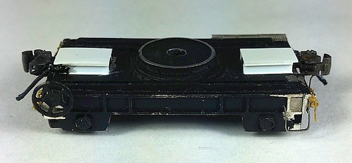
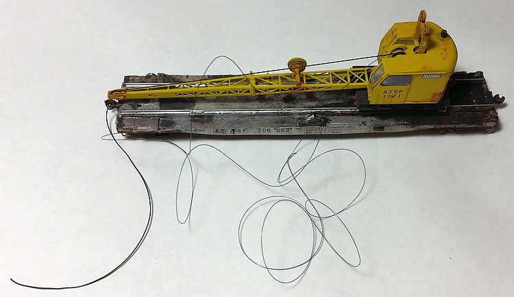
Below: I've modeled the crane lashed to its flat car in "transport mode" - the crane cannot be separated from the car.
This way, I can run the whole thing in a MoW train without fear of the fragile crane falling off and getting damaged.
My one concern is it's rather top-heavy thanks to the all-metal crane, so I'll keep a close eye out as it rolls *slowly* along.
This close-up highlights the weathering, as well as the scratch-built tie-down equipment and hard-stop rail clamps (red).
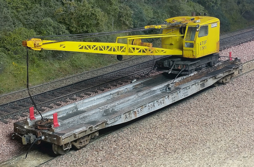
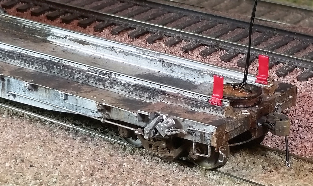
Below: I modified the flat car brake per the prototype. Also visible is the detailing of the rails, including flange bolts and joint bars.
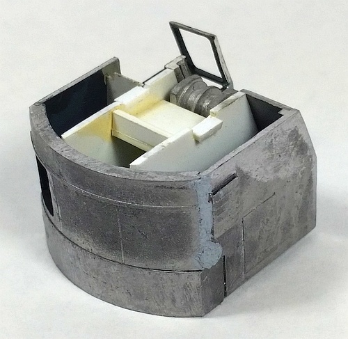
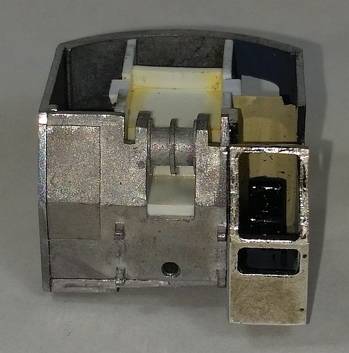
Below: I first built the carbody per Custom Finishing's instructions. But I added some styrene interior
"walls" to block the views through the windows, hiding the fact the interior is essentially empty. It's not
visible in these photos, but I added a set of brass wire control levers in front of the operator's seat.
"walls" to block the views through the windows, hiding the fact the interior is essentially empty. It's not
visible in these photos, but I added a set of brass wire control levers in front of the operator's seat.
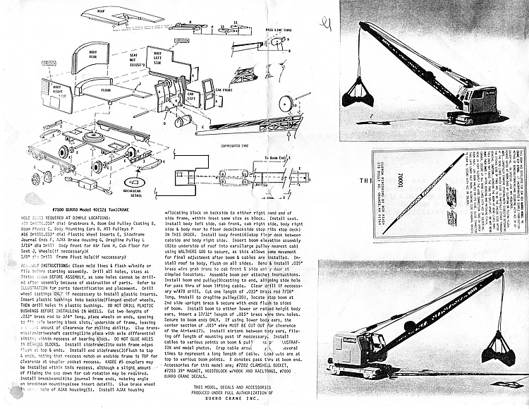
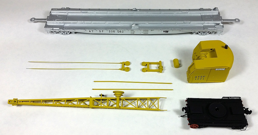
Right: This is the extent of the kit
instructions from Custom Finishing.
Needless to say, only experienced
modelers need apply. The kit
includes the etched-brass boom
but no "end toys" for the crane.
Those are available separately,
such as the set shown below.
instructions from Custom Finishing.
Needless to say, only experienced
modelers need apply. The kit
includes the etched-brass boom
but no "end toys" for the crane.
Those are available separately,
such as the set shown below.
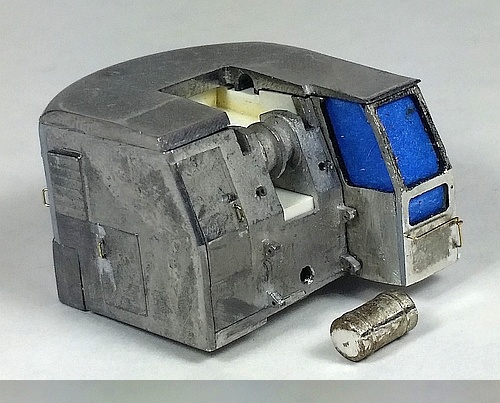
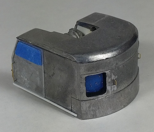
Left: I made a cab door from 0.015" clear sheet styrene and a lower
door track from strip styrene. I masked off the door's window area so
it will remain clear after painting.
Below: Before painting, I masked off the interior to prevent yellow
paint from over-spraying through the windows. The roof was
temporarily attached for painting using small dots of canopy glue.
I needed the roof to be removable to add the window glazing later.
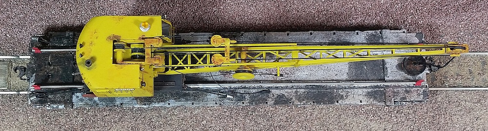
I built my Model 40 crane as a set of sub-assemblies including the carbody, the
underframe, the boom, and the lifting pulleys. These sub-assemblies remained separate
all the way through weathering, and were then assembled in place on the MoW flat car.
underframe, the boom, and the lifting pulleys. These sub-assemblies remained separate
all the way through weathering, and were then assembled in place on the MoW flat car.
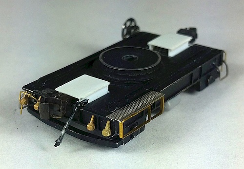
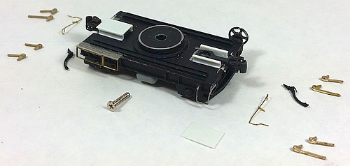
Below: Next was the underframe, also built per the instructions. But I
added lots of details, including scratch-built coupler pockets, etched
platform with strip-brass framing, wire cut levers, flat wire stirrup
steps, and a small reservoir shaped from gray styrene sprue
material. For the tie-down loops I used brass N-scale F-unit nose
lift lugs (Miniatures by Eric part number NL12). The brake line air
hoses came from my scrap box - I don't recall the brand.
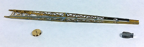
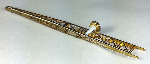
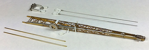
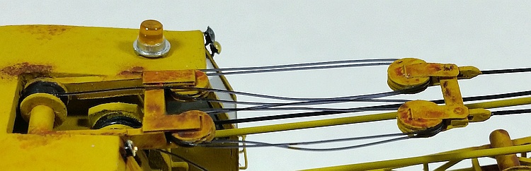
Below: I assembled the etched brass boom per its instructions using ACC adhesive. But I then finished the corners with strip
styrene and filler putty, filed and sanded smooth.
The big side pulley from the kit was crudely cast, so I ordered a brass 8mm sheave pulley from a ship modeling webstore
and used that instead. To its inside I glued a smaller circle of styrene and a styrene rod "axle" mounted across the boom.
To the pulley's outside I glued a steel washer found in my bins of stuff in the garage to approximate the shape of the prototype.
The lower right photo shows more detail added to the boom for another small cross-axle and "dangling" pulley, scratch-built
from styrene. Also visible are the hydraulic lifters I added, made from heavy brass wire. The vertical styrene strip supports
seen here were later replaced with brass strip for sturdiness.
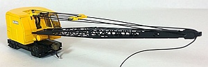
Around 2015 I had the opportunity to buy an assembled and painted Model
40 crane from Custom Finishing, which they'd built for a customer who never
paid for it. That model was fine (right), but it still lacked the "show piece"
detail I wanted. So I used it as a "practice" model for improving the cabling,
window glazing, and other details. Having regained confidence in these
aspects, I re-started my "real" crane in 2020 during the COVID-19
stay-at-home. Thank goodness for an indoor hobby!
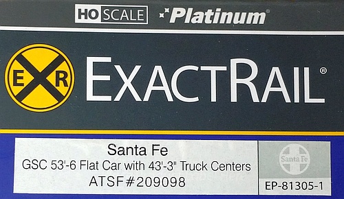
As it turned out, waiting so long to finish the crane model was a good thing,
for in the interim a much more accurate flat car model became available
from ExactRail. Sometimes things just work out, right?
40 crane from Custom Finishing, which they'd built for a customer who never
paid for it. That model was fine (right), but it still lacked the "show piece"
detail I wanted. So I used it as a "practice" model for improving the cabling,
window glazing, and other details. Having regained confidence in these
aspects, I re-started my "real" crane in 2020 during the COVID-19
stay-at-home. Thank goodness for an indoor hobby!
As it turned out, waiting so long to finish the crane model was a good thing,
for in the interim a much more accurate flat car model became available
from ExactRail. Sometimes things just work out, right?
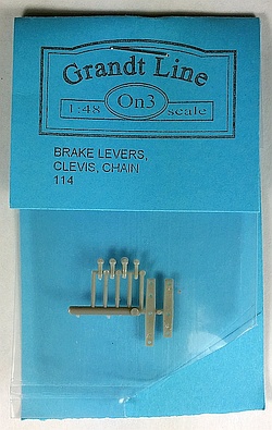
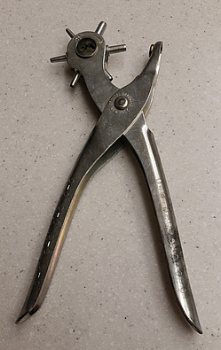
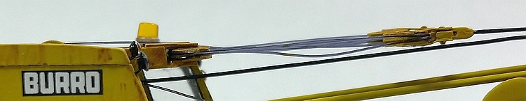
Below: The most intricate work involved the lifting pulley sub-assemblies. The cast metal parts from the kit were not detailed enough
for my goals, especially the pulleys which were just round blobs with no grooves for the cables. I scrapped those and made new
pulleys from sheet styrene. Using a multi-size hole punch (center) on 0.010" styrene, I punched out larger circles for the center and
outer layers, and smaller circles to go in-between (sandwich style) to form grooves once the layers were stacked. This was tedious
but it worked out OK. I then scratch-built brackets to hold the pulleys, attached to crossbars. The "floating" pulley mechanism
connects to the end of the boom using two lengths of brass wire. To attach these wires at either end, I used Grandt Line (now under
San Juan Details) part number 114 O-scale clevis castings (right). These are the gray parts in the photos on the left, which are a
U-shape and were glued onto the "floating" crossbar. The ones on the boom end are visible in the photo above.
At this point I painted the sub-assemblies primer gray. The underframe was then painted black, and I used Floquil ATSF Yellow on the
carbody, boom, and pulleys. I gloss-coated the carbody before applying the decals. The Burro logo decals came from Custom Finishing,
while the reporting marks are individual characters from a Microscale lettering set. A spray of dull-cote locked down the decals.
See below for the weathering and final assembly processes.
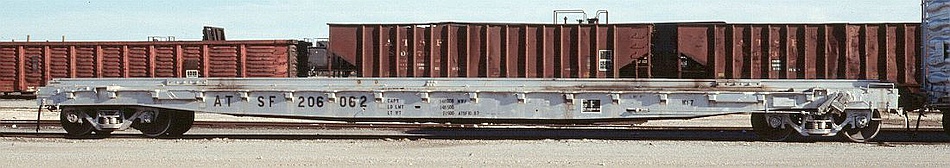
My model of MoW flat car 206062 represents a Santa Fe WT-7 class welded car. From
what I can piece together from photos found on the internet, these cars were upgraded
from earlier classes starting around 1989, a perfect fit for my modeling era of 1989-1995.
Above: This prototype photo, dated May 1989, was the inspiration for my model. The still-clean car suggests
it was recently upgraded by Santa Fe shop forces. Changes included replacing the end-mounted vertical
brake wheel with a side-mounted low-profile ratcheting brake lever. This required a length of connecting
rod running externally along the sidesill, attached to a lever arm fitted through a slot in the sidesill.
Below: The box end from the ExactRail model I started with. This model is very well detailed and quite accurate.
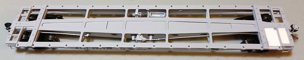
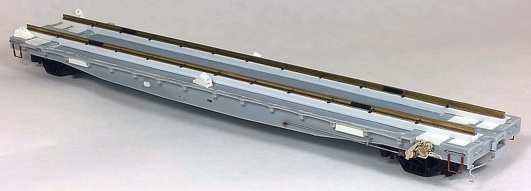
Below: The prototype has a steel deck, so I did not use the laser-cut wood deck that came with the model.
Instead, I filled the end openings with styrene, seen here at the far right end. Originally I thought I'd save
some work by using a pre-decorated car, but I ended up stripping off the factory paint after realizing the
road number was not correct for my purposes, and also the need to make changes to the sidesills.
Note the vertical brake wheel at the right end - this was removed before stripping the paint.
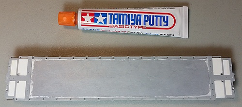
Right: To model the central area of the steel deck, I glued down a
big rectangle of 0.005" styrene sheet. Unfortunately the styrene glue
deformed the very thin styrene - it sort of sunk into the big openings.
To fix this, I put down several thin layers of Tamiya modeling putty,
sanding each layer smooth. If I had to do this over again, I'd find
some other way to model the steel deck.
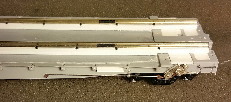
Right: I replicated the side-mount
ratchet brake using Details West
part HB-1016. A portion of the
overhanging deck was removed.
I drilled a hole through the metal
part below the pulley, and
threaded a plastic chain piece
with a clevis on the end (don't
recall the brand, it might be a
Grandt Line part?). I cut a small
slot in the sideframe and glued in
half a brake lever. Then I added
a steel wire connecting rod,
supported by a wire eye bolt.
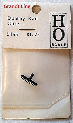
Also visible on the deck rails are
the black Grandt Line brand 5155
rail clips (below) and Central
Valley brand joint bars.
part HB-1016. A portion of the
overhanging deck was removed.
I drilled a hole through the metal
part below the pulley, and
threaded a plastic chain piece
with a clevis on the end (don't
recall the brand, it might be a
Grandt Line part?). I cut a small
slot in the sideframe and glued in
half a brake lever. Then I added
a steel wire connecting rod,
supported by a wire eye bolt.
Also visible on the deck rails are
the black Grandt Line brand 5155
rail clips (below) and Central
Valley brand joint bars.
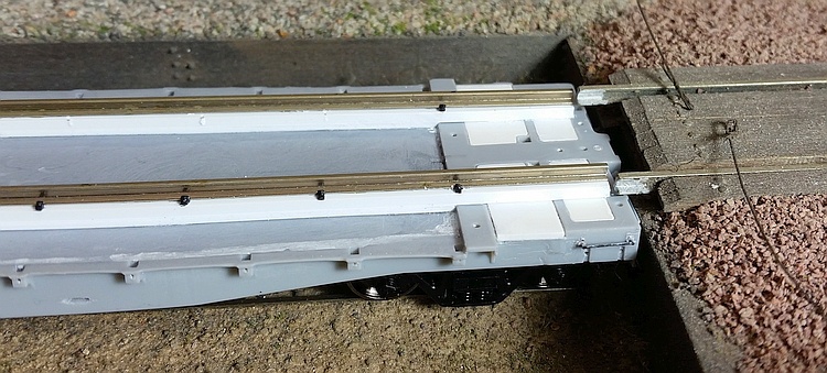
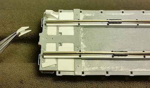
Below: Some of the rail clips on the rail flanges have been installed. The loading ramp trackage was
installed over 20 years ago and turned out to be not quite the correct height and also not perfectly level
side-to-side. To get the car's rails to align more closely, I used some modeler's license and raised its
rails above the car deck on heavy strips of styrene. The new brake gear has not yet been installed.
Right: Santa Fe installed unique deck "cleats" to lash
down the Burro crane for transport. I scratch-built
something similar from sheet styrene and tubing.
down the Burro crane for transport. I scratch-built
something similar from sheet styrene and tubing.
Below: The completed flat car before primer. I filled
the small oval openings in the sidesills per the
prototype photo. I added styrene blocks between
the 3rd and 4th stake pockets from each end - I don't
know what purpose these served on the prototype
cars, but I went ahead and replicated it. I also
replaced the stirrup steps with Tichy Trains parts, as
I had damaged the original stirrups during stripping.
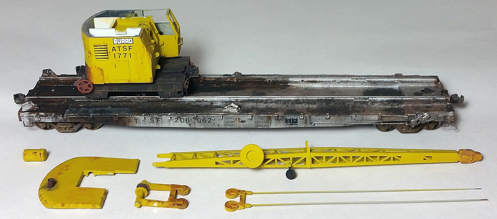
Once painted, I weathered the flat car and the Burro crane sub-assemblies using a variety of mediums
including artist oils, powdered chalks, and airbrushing. A spray of dull-cote locked down the weathering.
The crane was assembled in-place on its flat car, followed by the final details.
including artist oils, powdered chalks, and airbrushing. A spray of dull-cote locked down the weathering.
The crane was assembled in-place on its flat car, followed by the final details.
I painted the flat car with Tru-Color TCP-013 Aluminum, including the trucks and underframe.
The reporting marks are individual characters from a Microscale lettering set.
The reporting marks are individual characters from a Microscale lettering set.
Above: The painted and decaled sub-assemblies ready for weathering. The flat car has Walthers drawbars installed temporarily for handles
during painting. The crane's brake wheel and underframe tie-down loops were brush-painted SP Scarlet, creating a nice faded appearance.
Below: The finished weathering. I used artist oils (Burnt Sienna and Burnt Umber) for the streaky rust areas. After applying tiny dots of paint
using a toothpick, I wetted a flat brush in mineral spirits and made a single, quick, downward stroke over the spots to create the streaks.
I then cleaned the brush with mineral spirits before making a second stroke when necessary. Cleaning the brush before each stroke prevents
extraneous paint from transferring from the brush to the model.
For the heavy oily/greasy grunge on the flat car, I brushed on some artist oils into the area I wanted grungy, and then dusted black
and brown powdered chalks into the oils. Lighter oil spots were dabbed on using a thinned mixture of black and brown paint.
On the flat car trucks, I brushed on some mineral spirits and then dusted on brown, black, and rust chalks. This helps more chalk
stick to the trucks for a heavier weathering effect. Once the weathering was done, everything got a spray of dull-cote to lock it down.
Note also the crane carbody roof has been removed so the lifting pulley piece and window glazing can be installed.
The roof was then re-attached using canopy cement which dries clear, and a rusty exhaust stack has been installed (styrene tube).
The masking tape has also been removed from the door window.
Right: To attach the crane to the
flat car, I drilled a hole through the
flat car's metal centersill and also
through the crane's underframe.
I then drilled and tapped a hole into
the carbody's central pivoting pin.
I used a long machine screw that
runs up through the flat car, through
the crane underfame, and threads
into the carbody.
I attached the boom using small
bits of brass wire hooked through mounting holes in the boom and
the carbody. The fuel tank was
then installed between the boom.
The main cable is a crafting
product, 0.5mm rubber string.
I later tied this through a wire loop
attached to the "electromagnet"
that is then glued to the flat car,
further attaching crane to flat car.
The small cable that loops around the big side pulley is 0.010" nylon
thread that came with the Custom Finishing kit.
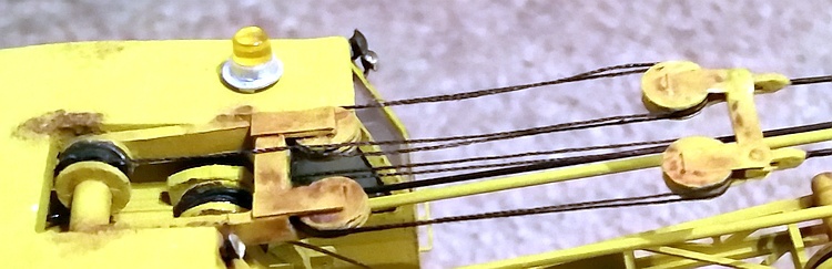
Right: For the first attempt at the
lifting pulley cabling, I tried using
the 0.010" nylon thread that came
with the Custom Finishing kit. This
was tediously threaded around the pulleys in sequence.
I was not happy with the result -
the material tended to make odd loopy shapes, even after gluing
with ACC.
And, yes, that beacon is crooked.
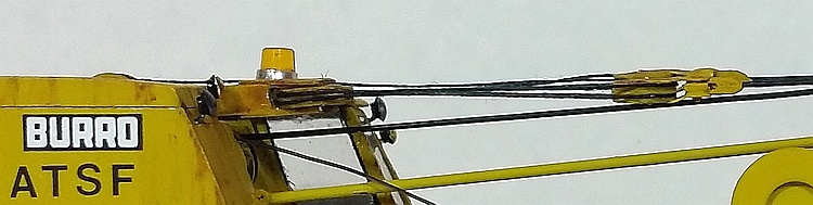
Right: After some hesitation and
deep breathing, I decided to try
again. I cut through the nylon and
used small dabs of acetone to
remove most of the ACC from
the pulleys. I did break one pulley
in the process but was able to
repair it. Another deep breath.
I then used black sewing thread
for the cabling. I first ran some
candle wax over the thread to
reduce the "fuzziness", which was
mostly successful. The thread
is more flexible so it holds its
shape better, though it's still
not perfect. I decided this was
as good as it was going to get.
I also straightened out the beacon!
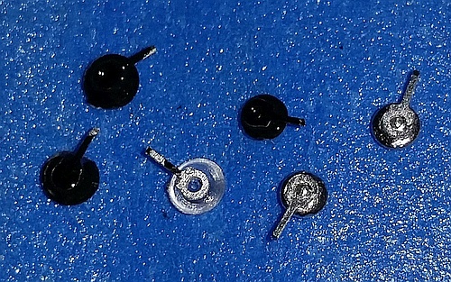
Below: To simulate the small work lights mounted to the carbody,
I glued metal lift rings to the backs of headlight lenses and then
painted them black on the backside only. The larger lights are
lenses from a Detail Associates JW1709 set, the smaller lights
are no-longer-available MV Lenses from my parts stash.
I then bent the "stem" to whatever angle was needed, and
ACCed them into holes drilled into the carbody.
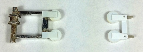
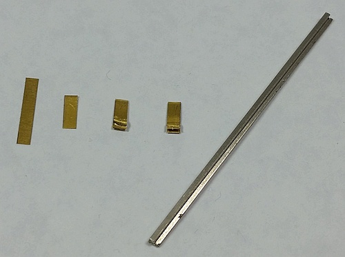
Below: Here is how I made the hard-stop rail clamps attached at
either end of the flat car (painted red). From left to right: I cut a long
rectangle from sheet brass; folded it in half; used tweezers to
rough-shape the clampy end; used the tweezers to pinch the part
around a piece of rail to get the final clamp shape.
I glued these brass parts to the flat car rail ends with ACC, and
added Central Valley joint bars cut in half before painting them red.
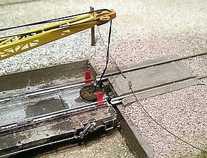
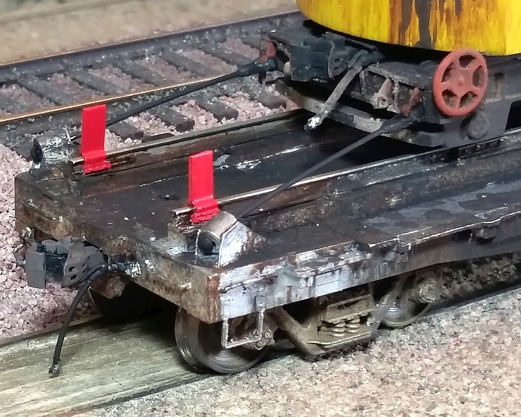
Right: Here are the hard-stop
rail clamps once installed.
For the tie-down cables, I used
optic fiber material. Heating the
end forms a "mushroom" head,
which I threaded into the flat
car's tie-down cleats. At the crane
end, I used more Grandt Line
clevis parts fitted over the
Miniatures by Eric brass tie-down
loops. The optic fibers are glued
into the holes in the clevises, and
brush-painted black.
-- About
-- Contact
-- Diesels
-- Links
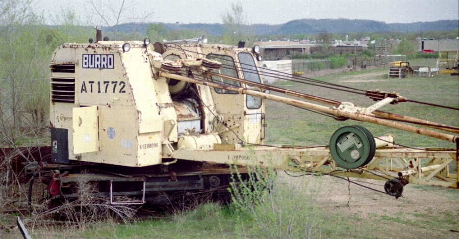
Below: This prototype photo of retired ATSF 1772 Model 40 Burro crane found on the internet (thanks
to whomever posted it!) provided tons of information for detailing the carbody, lifting pulleys, and boom.
to whomever posted it!) provided tons of information for detailing the carbody, lifting pulleys, and boom.
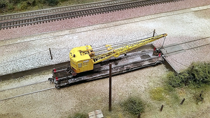
Below: A similar shot of my model on the main line of my Glen Frazer Free-mo module.
entire website copyright Gregg Fuhriman
created with CoffeeCup Visual Site Designer
created with CoffeeCup Visual Site Designer
-- Layouts
-- Modules
-- Signalling