|
|


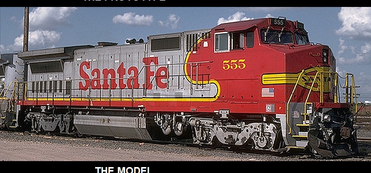


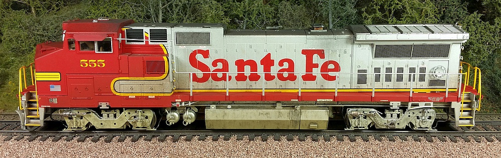
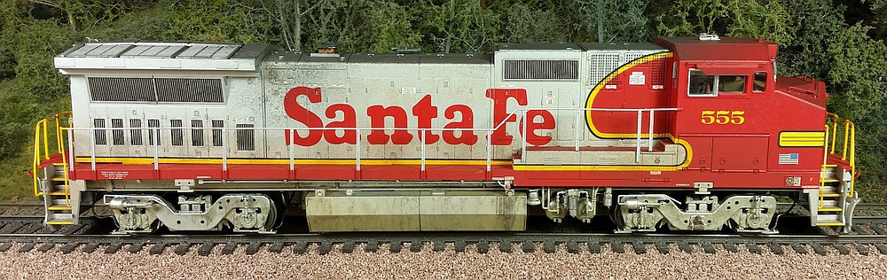


ATSF DASH8-40BW 555
This is a pre-decorated Atlas product that I upgraded with added details, decals, and weathering.
I also replaced the stock LED lights to make them brighter, including the ditch lights.
This is a pre-decorated Atlas product that I upgraded with added details, decals, and weathering.
I also replaced the stock LED lights to make them brighter, including the ditch lights.
Right: Here is the prototype loco
circa 1992, in about the same
condition as I've modeled.
circa 1992, in about the same
condition as I've modeled.
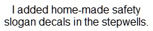
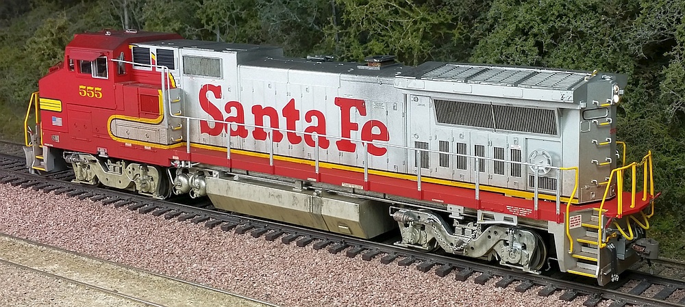
Below: My model is lightly weathered to represent a unit just a year or two old. I washed diluted India ink over the
trucks and fuel / air tanks, then lightly dusted on powdered weathering chalks for the road dust effect. I brushed
diluted black paint into the various grills to give them more "depth". A spray of dull-cote ties everything together.
trucks and fuel / air tanks, then lightly dusted on powdered weathering chalks for the road dust effect. I brushed
diluted black paint into the various grills to give them more "depth". A spray of dull-cote ties everything together.
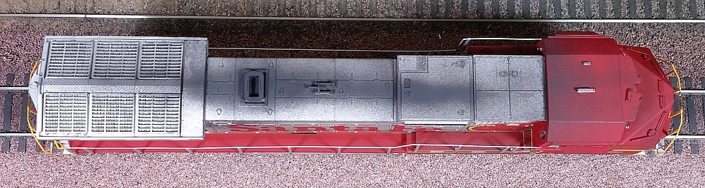
Above: Artist's oil paints were dabbed onto the exhaust stack to capture the burned,
rusty effect so common on GE locomotives.
Below: The top got some diluted black airbrushed over the exhaust stack and adjacent areas.
Black powdered weathering chalk was lightly dusted over the entire top and affixed with dull-cote.
rusty effect so common on GE locomotives.
Below: The top got some diluted black airbrushed over the exhaust stack and adjacent areas.
Black powdered weathering chalk was lightly dusted over the entire top and affixed with dull-cote.
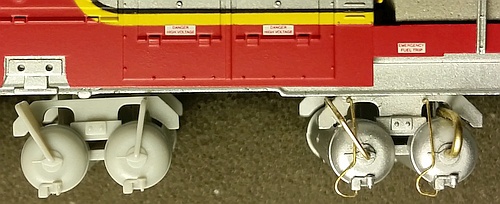
Right: I upgraded the left-side air tank piping by carving off the cast-on
plastic details (left - original part), drilling holes, and then adding
custom-formed brass wire in various gauges (right - finished upgrade).
plastic details (left - original part), drilling holes, and then adding
custom-formed brass wire in various gauges (right - finished upgrade).
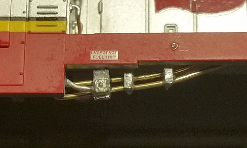
Below and Below Right: On the left side, below the sill
just behind the cab, I added new brass-wire piping to
model a detail quite visible on the prototypes. These are
tucked in behind a Details West fuel cutoff detail part.
just behind the cab, I added new brass-wire piping to
model a detail quite visible on the prototypes. These are
tucked in behind a Details West fuel cutoff detail part.
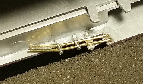
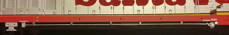
Right: On the right side below the
walkway, I used a Details West
piping kit to add another detail
that stands out on the prototypes.
The kit consists of cast metal
brackets and brass wire that
threads through them, simulating
parallel pipes/conduits. Another
Details West fuel cutoff part was
also added. These details were
brush painted Aluminum.
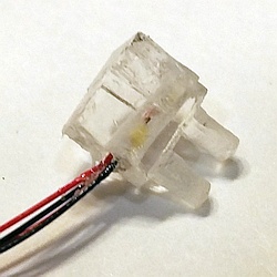
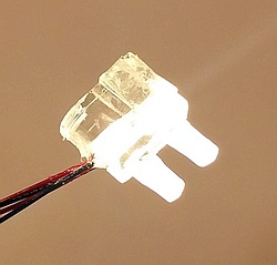
Right: I replaced the stock LED
lights with small SMT LEDs that
have wires pre-installed. I drilled
a vertical hole in the Atlas light
insert and glued in the LEDs
using a clear rubber cement.
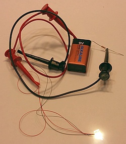
Far Right: to test LEDs during
the install process, I use a 9-volt
battery and a 1000 ohm resistor
jammed into one of the contacts.
The clip leads connect the
battery/resistor to the LED wires.
The LED-equipped light inserts
were then installed back into the
shell and secured with clear
rubber cement. Liquid electrical
tape was used to block light leaks.
lights with small SMT LEDs that
have wires pre-installed. I drilled
a vertical hole in the Atlas light
insert and glued in the LEDs
using a clear rubber cement.
Far Right: to test LEDs during
the install process, I use a 9-volt
battery and a 1000 ohm resistor
jammed into one of the contacts.
The clip leads connect the
battery/resistor to the LED wires.
The LED-equipped light inserts
were then installed back into the
shell and secured with clear
rubber cement. Liquid electrical
tape was used to block light leaks.
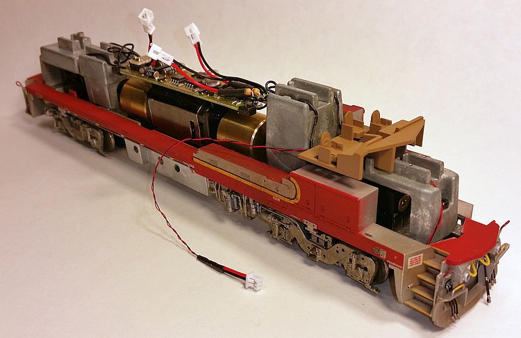
Right: Since the LEDs are now
mounted to the shell instead of
the drive, I added 2-pin micro-
connectors and current-limiting
resistors soldered to the DCC
decoder board. The mating
connectors are soldered onto
the LED leads.
This way, the shell-mounted LEDs
can be easily disconnected from
the drive-mounted decoder when
the shell needs to be removed
for repair or maintenance.
-- About
-- Contact
-- Diesels
-- Links
entire website copyright Gregg Fuhriman
created with CoffeeCup Visual Site Designer
created with CoffeeCup Visual Site Designer
-- Layouts
-- Modules
-- Signalling